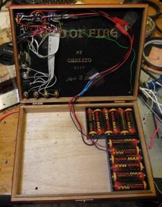
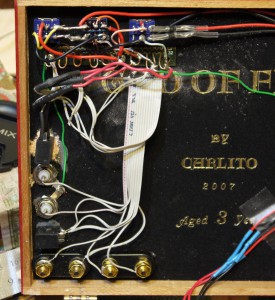
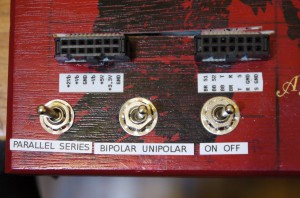
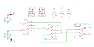
As a kid, I always like those 300-in-One Electronic Project Lab toys. Although not really useful for real work, it was nice to have everything in one place. I decided to attempt to build one the way I want it to be. So far, I just have the power supply and external connectors set up. I can set it to unipolar +9V or +18Vor bipolar +9/GND/-9 volts for analog work. Plus dedicated +5V and +3.3V rails. I used the dead simple method of generating a bipolar supply, I simple used two battery packs in series. Eventually I may upgrade to some sort of switcher circuit, but you can’t beat the pair of batteries for a low noise power source.
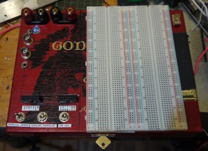
I included easy attachment points for connecting an oscilloscope or multimeter and phono jacks for routing audio signals and testing homebrew audio effects. By putting them near the edge I can move the board around without the cables interfering with teh breadboard or falling out.
I am using a random cigar box, they make great project boxes and can be gotten cheaply or for free from cigar shops. It turned out quite attractive if I do say so with its red/black motif. I wonder if I can find solid black breadboards to keep it on theme.
After this, I will add some panel meters and LEDs, some of the more common things needed when breadboarding. I am leaning towards a rotary encoder, a couple buttons, and a Voltmeter at the moment. Unlike the 300-in-1 style kit, I will have proper debouncing and quadrature circuitry built in to give nice clean logic level outputs and high impedance inputs.


Two inexpensive panel meters fit quite nicely in a Hammond stomp box case. Perfect for a voltage and current meter.
Continue Reading »
I show how to use a pair of magnets to temporarily mount a surface mount chip to a breakout board.
Surface mount chips are becoming more common nowadays but they are harder to use for prototyping not being breadboard friendly. Using a simple SMD breakout board (like one of these ) and some powerful magnets (I use these ones
 ) you can conveniently and easily temporarily attach SMD chips to the breakout board.
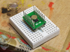
You simply use a magnet to hold the chip onto the board.
Continue Reading »
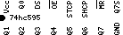
A while ago I started labeling my chips when breadboarding. Having a bin of properly labeled common jelly bean chips is just an extremely useful thing to have in arms reach when prototyping or experimenting with circuits. One thing that is annoying is having the decoupling capacitors right over the top of the chips blocking the layout and not doing a very good job decoupling due to it’s large leads adding dreaded inductance.
Then after spilling some parts I noticed this.
The axial decoupling caps fit directly in the grooves in the breadboard! Let’s take advantage of that….
Continue Reading »
Have a big coil of wire you don’t know the length of? don’t bother measuring it, just measure how long it takes for a signal to go through it and multiply by the speed of light and there you go.

Here is a simple one chip time-domain reflectometer. It consists of a pulse generator that can drive pulses with a rise time on the order of a nanosecond. I hook it to just one end of the unknown wire and set it off, the first step you see on the screen is my generated pulse. the next step is my signal being reflected off the other end of the cable and coming back to hit me. I have the meter set to 25 nanoseconds a division, so it took about 75 nanoseconds for the signal to come back, rule of thumb for the speed of light is a foot a nanosecond in vacuum and about 2/3 of that for an electric signal in copper. so 75 feet * 2/3 = 50 feet, and since the signal had to go down the wire and come back, you end up with 25 feet of wire in my unknown length coil.
The circuit is based on the one on this page http://www.epanorama.net/circuits/tdr.html which also has more discussion on how a TDR works.
Resistance substitution boxes are a well known feature of any electronics lab and a common beginning project, allowing you to dial in a specific resistance measured in ohms directly. The inverse of a resistance box is the conductance box, allowing you to dial in a specific conductance measured in siemens. The most straightforward method of creating a resistance box is to use 10 position dials to connect resistors in series, a conductance box can be made by using BCD to connect resistors in parallel.
I used some dials that were BCD or binary coded decimal that had connections for one,two,four, and eight producing a binary digit by connecting the corresponding bits in parallel. While this form of dial cannot be directly used for a resistor box, it can be used to dial in conductance directly in siemens. This is due to the fact that connecting resistors in parallel will increase their conductance, as opposed to series which increases resistance and decreases conductance.
Continue Reading »
It turns out the 6mm (1/4″) tape for the brother p-touch PT-1230PC computer controlled label maker is just about perfect for labeling PDIP ICs. I whipped up a small program to generate images from the chip pinouts and control the printer in raw mode to create labels.
Next step is to put a QR code on there that links to the data sheets.
A link to the very rough code is here, you will probably have to modify it to suit your situation: chip_ptouch.tar.gz
UPDATE
I have updated the tarball above to include printer control code generator to print the pngs in raw mode, more chips, and a README with sample usage.
How to modify your reprap to use cheaper, more reliable hall effect sensors rather than physical switches.
Given how both physical switches and optical sensors have their own issues for using as reprap endstops, I decided to experiment with Hall effect sensors which detect the presence of a magnetic field. The idea being you place a magnet on your carriage, stick the sensor at one end and when the magnet gets close, you get a signal. Very simple and robust, no moving parts, no need for precise placement, just get the magnet at just the right distance and it triggers.
I was able to find these A3144 hall effect sensors for 19 cents each. That’s right, cheaper than switches, cheaper than opto endstops, and superior to both. And there appears to be tons of suppliers for the things, so they are not going away anytime soon. They just have three pins, GND, Vcc, and signal. The signal is normally open collector, get a magnet close and it drains to ground. Now, when trying to figure out how to interface this with the standard RAMPS hardware, I came up with the below circuit.
Continue Reading »
So, it turns out I am the winner of the 2008 Underhanded C Contest. The goal of the contest is to write some straightforward C code to solve a simple task, incorrectly. In particular, you had to introduce a hidden security flaw that would stand up to code review and not stand out at all. This is different than the Obfuscated C contest in that you want your program to look straightforward and that it does one thing, when in fact it does another.
The goal this year was to write a leaky image redaction program. Given an input image in PPM format and a rectangle, it would spit out the image with the rectangle blacked out, perhaps hiding sensitive information. The tricky part was that you had to leak the redacted information. There are more details in the problem specification.
So, before I go on, here is my complete entry. See if you can figure out how the information is leaked before reading further if you like.
/*
 * This is a simple redactor, it accepts a plain text ppm file, a set of
 * coordinates defining a rectangle, and produces a ppm file with said
 * rectangle blacked out.
 *
 * Usage: redact in.ppm x y width height > out.ppm
 */

int
main(int argc, char *argv[])
    {
        if(argc != 6) {
            fprintf(stderr, "usage: redact in.ppm x y width height > out.ppm\n");
            exit(1);
        }

    // process command line arguments
    int rx = atoi(argv[2]), ry = atoi(argv[3]), rwidth = atoi(argv[4]), rheight = atoi(argv[5]);

    FILE *ppm = fopen(argv[1],"r");
    if(!ppm) {
        perror(argv[1]); exit(1);
    }

    //read the ppm header
    unsigned width,height,maxdepth;
    fscanf(ppm,"P3\n%u %u\n%u\n", &width, &height, &maxdepth);
    printf("P3\n%u %u\n%u\n", width, height, maxdepth);

    //current locations
    int x = 0, y = 0, ws = 0;

    //fixed buffer size to avoid overflow
    char buf[BUFSIZE], *c;

    while(fgets(buf,BUFSIZE,ppm)) {
        for(c = buf;*c;c++) {
            if(isdigit(*c)) {
                if(!ws) {   // new number, increment location.
                    ws = 1; x++;
                    if(x >= width * 3) {
                        y++; x = 0;
                    }
                }
                if(x > rx * 3 && x <= (rx + rwidth) * 3 && y > ry && y < ry + rheight)
                    putchar('0');
                else
                    putchar(*c);
            }  else {
               ws = 0;
               putchar(*c);
            }
        }
    }
    return 0;
} |
/*
* This is a simple redactor, it accepts a plain text ppm file, a set of
* coordinates defining a rectangle, and produces a ppm file with said
* rectangle blacked out.
*
* Usage: redact in.ppm x y width height > out.ppm
*/
int
main(int argc, char *argv[])
{
if(argc != 6) {
fprintf(stderr, "usage: redact in.ppm x y width height > out.ppm\n");
exit(1);
}
// process command line arguments
int rx = atoi(argv[2]), ry = atoi(argv[3]), rwidth = atoi(argv[4]), rheight = atoi(argv[5]);
FILE *ppm = fopen(argv[1],"r");
if(!ppm) {
perror(argv[1]); exit(1);
}
//read the ppm header
unsigned width,height,maxdepth;
fscanf(ppm,"P3\n%u %u\n%u\n", &width, &height, &maxdepth);
printf("P3\n%u %u\n%u\n", width, height, maxdepth);
//current locations
int x = 0, y = 0, ws = 0;
//fixed buffer size to avoid overflow
char buf[BUFSIZE], *c;
while(fgets(buf,BUFSIZE,ppm)) {
for(c = buf;*c;c++) {
if(isdigit(*c)) {
if(!ws) { // new number, increment location.
ws = 1; x++;
if(x >= width * 3) {
y++; x = 0;
}
}
if(x > rx * 3 && x <= (rx + rwidth) * 3 && y > ry && y < ry + rheight)
putchar('0');
else
putchar(*c);
} else {
ws = 0;
putchar(*c);
}
}
}
return 0;
}
Continue Reading »
Recently I have been building the cupcake CNC 3d printer as a stepping stone for getting involved with the reprap project. This was the first time I have tried soldering surface mount components, and I must say it turned out to be quite straightforward and easy using the hotplate reflow method. The main issue was actually more psychological than anything, and that is that I wasn’t able to test the circuits incrementally as I create them. Normally, I alternate placing a few components and testing connections with a multimeter throughout a fabrication, however, with the hot plate reflow method you pretty much have to do all of the surface mount components in one go, and once you start soldering non surface mount components, you can’t really go back to using the hot plate again.
This issue was somewhat compounded in the design of the cupcake CNCs electronics in that the first testable configuration involved many different components, an ardunio motherboard, a stepper driver, host software running on a PC, and the various interconnects. Coming up with a way to test the stepper driver boards independently of the rest of the system was quite useful. I whipped up the following simple circuit to test the stepper boards. None of the component values are very important, C1 is a debouncing capacitor for the pushbutton, R1 is a pull down resistor, and R2 is to protect the LED.P1 is a power header that accepts a floppy connector power supply cord from the same PC supply that powers the stepper driver.