Resistance substitution boxes are a well known feature of any electronics lab and a common beginning project, allowing you to dial in a specific resistance measured in ohms directly. The inverse of a resistance box is the conductance box, allowing you to dial in a specific conductance measured in siemens. The most straightforward method of creating a resistance box is to use 10 position dials to connect resistors in series, a conductance box can be made by using BCD to connect resistors in parallel.
I used some dials that were BCD or binary coded decimal that had connections for one,two,four, and eight producing a binary digit by connecting the corresponding bits in parallel. While this form of dial cannot be directly used for a resistor box, it can be used to dial in conductance directly in siemens. This is due to the fact that connecting resistors in parallel will increase their conductance, as opposed to series which increases resistance and decreases conductance.
There are a few reasons a conductance box might be more useful than a resistance box in a given situation. A conductance box naturally starts with an open circuit and gradually adds conductivity allowing more current to flow as you dial upwards, a resistance box does the opposite. starts with a closed circuit and you gradually dial up the resistance. Each approaches but never reaches the other extreme, a resistance box never simulates an open circuit and a conductance box never simulates a closed one as they would be “infinite” in each scale. In many circuits you encounter resistance in the inverse position, such as I = V/R, you can instead say V=IK where K is conductance. For instance oscillators and linear regulators guiding equations are often more easily expressed in terms of conductance. By dialing in conductance, you are in effect dialing in inverse resistance directly, allowing proportional control of frequency or current in those situations. A conductance box will naturally handle higher currents than a resistance box, whereas a low resistance in a resistance box may have to have all the current go through a single low ohm resistor, in a conductance box it is split among many parallel resistors.
First I solder the resistors to the dials. rather than use exact resistor values, you can create the ones you need by paralelling up multiple of a single value of resistor. for instance, for the millisiemens digit of conductance you would use 1k ohm resistors, connecting a single one to the one bit, two in parallel to the two bit, and so forth. giving resistances of 1k, 500ohm, 250ohm, and 125.5ohm for the digits. this gives one, two, four, and eight millisiemens respectively which can be added by combining the resistances in parallel.
I am creating a dial for millisiemens, so have 1k, 100ohm, and 10 ohm digits built. But the range can be extended trivially in either direction. The digits are stacked as shown
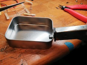
Then I use a nibbler to cut appropriate slots in a small metal enclosure. These style of enclosures can be gotten for tens of cents online and are handy for a variety of projects.
Then I put the dial as well as a standard bananna jack on the enclosure, soldering the common pin of each digit to the metal case and the negative bananna jack, and the other ends of the resistors together to the positive jack. The conductance box is non directional, so the positive and negative terminals don’t matter except the black negative terminal is connected to the enclosure shield as is conventional.
Then just tack solder on the lid and enjoy your conductance box able to dial in a specific conductance value in millsiemens. since it has three digits, it can be dialed up to 999 millisiemens or roughly one siemens which is equivalant to one ohm of resistance.
Next I’m going to add three more digits and give it a microsiemens range. which will add 10k, 100k, and 1M stages and cover the entire range of common conductances encountered.


