How to modify your reprap to use cheaper, more reliable hall effect sensors rather than physical switches.
Given how both physical switches and optical sensors have their own issues for using as reprap endstops, I decided to experiment with Hall effect sensors which detect the presence of a magnetic field. The idea being you place a magnet on your carriage, stick the sensor at one end and when the magnet gets close, you get a signal. Very simple and robust, no moving parts, no need for precise placement, just get the magnet at just the right distance and it triggers.
I was able to find these A3144 hall effect sensors for 19 cents each. That’s right, cheaper than switches, cheaper than opto endstops, and superior to both. And there appears to be tons of suppliers for the things, so they are not going away anytime soon. They just have three pins, GND, Vcc, and signal. The signal is normally open collector, get a magnet close and it drains to ground. Now, when trying to figure out how to interface this with the standard RAMPS hardware, I came up with the below circuit.
 |
| From Hall Effect |
That’s right. The three pins are _exactly_ the same pins, in the same order, that RAMPS expects its endstops to have. The only setup you need is a 3 pin jumper cable you can stick the sensor in. Simple servo cables from pololu or any RC store work perfectly and there is no need to solder anything. When looking at the larger flat side of the sensor, the left leg is the signal so should be oriented towards the outside of the RAMPS board when plugged in.
Here is it next to the large switch and printed holder it is replacing.
 |
| From Hall Effect |
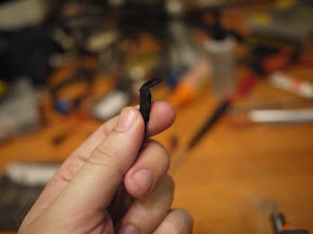
Just wrap it in electrical tape to insulate its wires.
 |
| From Hall Effect |
Then attach it to your shaft with one face pointing towards your carriage. You can then affix the magnet to your carriage however you want, I just let the magnet stick to the motor body itself for the Z axis, but glue, tape, or a bracket would also work. Just whatever you do, make sure both the magnet and sensor are very secure to get repeatability in your measurements. Also, the sensor only detects the magnetic field in one direction, so make sure the proper (north or south) pole is facing the sensor! Just test it before permanently glueing anything. 🙂
 |
| From Hall Effect |
 |
| From Hall Effect |
Now, the Hall effect triggers by sinking the signal to ground, so be sure to enable the pull up resistors for your endstops and set the “INVERT_ENDSTOP” flag in your firmware.
Since I was playing around with these hall effect sensors, I decided to create a little handheld magnetic field sensor that would allow me to test for the presence and polarity of magnet fields and came up with this handy device.
 |
| From Hall Effect |
While playing around testing various magnets, I re-discovered something interesting, those throw away flexible refrigerator magnets are not actually just a plain magnet, but a repeating pattern of north and south poles that can be read with the sensor.
for 19 cents, this seems like a pretty useful little device. And there should be no reason to use mechanical or optical endstops anymore, these are way cheaper, more reliable and simpler.

Comments 5
Thanks for documenting this!!
After reading, I used these sensors to improve my solidoodle2 and made some adapters to mechanical endstops in the process:
http://www.thingiverse.com/thing:35569
Thanks again,
Posted 24 Nov 2012 at 11:40 am ¶Tarwin
Sorry i could not see how you connected the three wires to the RAMPS 1.4 which has two wires foe mechanical endstops. Where do you get the 5V to power it?
Posted 01 Dec 2012 at 9:17 am ¶Thanks
Eduardo
I bought some hall effect sensors and resistors for my MendelMax. I tried to wire it up, but it doesn’t seem to work.
How do you use these hall sensors with a Sanguinololu board? The Sang board works with normally closed mechanical endstops (only 2 wires).
I don’t understand how to wire the Hall effect sensor, as it has 3 wires. Please advise.
Posted 15 Feb 2013 at 2:51 pm ¶Not sure what’s going on with ThIngiverse ATM, but nice work – I’ve replaced all the endstops on my Mendel with the same sensors’ John’s using, and they work a treat. I’m also using some rare-earth magnets I had lying around, and they probably are overkill.
Posted 14 Jun 2013 at 12:39 am ¶@Eduardo and Chris
I haven’t seen a Sang board so I can’t comment on those but Ramps 1.4 definitely has three pin sockets for the endstops, one for 5v, one for 0v and one for the signal.
If the Sang only has two pin sockets then identify the feed required, ie whether it’s low or high. If it’s low then you have a gnd and signal so pick up the 5v from another pin elsewhere on the board and use this pin for all the 5v pins on your endstops, if it’s high then you have 5v and signal so pick up a 0v somewhere else on the board.
Keith
Posted 26 Sep 2013 at 4:42 am 