Recently I have been building the cupcake CNC 3d printer as a stepping stone for getting involved with the reprap project. This was the first time I have tried soldering surface mount components, and I must say it turned out to be quite straightforward and easy using the hotplate reflow method. The main issue was actually more psychological than anything, and that is that I wasn’t able to test the circuits incrementally as I create them. Normally, I alternate placing a few components and testing connections with a multimeter throughout a fabrication, however, with the hot plate reflow method you pretty much have to do all of the surface mount components in one go, and once you start soldering non surface mount components, you can’t really go back to using the hot plate again.
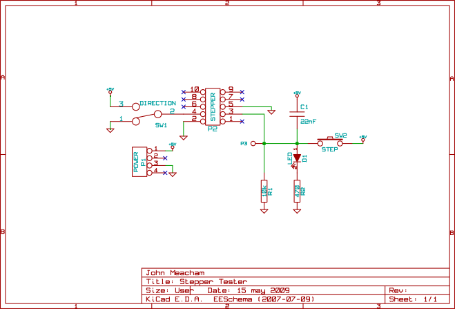
This issue was somewhat compounded in the design of the cupcake CNCs electronics in that the first testable configuration involved many different components, an ardunio motherboard, a stepper driver, host software running on a PC, and the various interconnects. Coming up with a way to test the stepper driver boards independently of the rest of the system was quite useful. I whipped up the following simple circuit to test the stepper boards. None of the component values are very important, C1 is a debouncing capacitor for the pushbutton, R1 is a pull down resistor, and R2 is to protect the LED.P1 is a power header that accepts a floppy connector power supply cord from the same PC supply that powers the stepper driver.

Comments 1
財布ルイヴィトン スーパーコピー 長財布2023年新作 ルイヴィトン スーパーコピールイヴィトン コピー,ルイヴィトン コピー 財布,ルイヴィトン コピー バッグ }}}}}}
Posted 04 Jun 2023 at 9:18 pm ¶https://www.bagssjp.com/menu/menu_product-3-194.html
https://www.bagssjp.com/menu/menu_product-196.html
https://www.bagssjp.com/product/detail-6544.html
https://www.bagssjp.com/product/detail-6865.html
https://www.bagssjp.com/product/detail-1261.html